V.7 Tutorial 7: More realistic simulations
This tutorial teaches how to build more realistic models, which include ions channels and synaptic mechanisms.
Start NMLPlay as explained previously (Tutorial II.B). Click on "Environment", then "Add" under the "AbstractNeurons window". Type Learning_Neuron for the name. Then select neuroml.model.cell.ModuleNeuron instead of neuroml.model.cell.AbstractNeuron. Then select Holger_modules.module.shmemneuron.LearningNeuronFactory as for the parameter of the ModuleNeuron. This allows selecting a class of neurons which can handle synapses and include ions channels. Select 2.5e-5 as for dt, 0.5 as for dv_trigger and -0.03 for minV_trigger. In order to have a spike generated, dv/dt must be greater than dv_trigger and the voltage must exceed minV_trigger.
In the "Channels panel", add a module channel. Name it LeakChannel . Select a Holger_modules.module.channels.LeakChannel as for the class parameter (Figure 28).
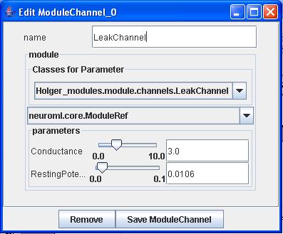
Figure 28: A leak channel
Create two other channels, respectively called KChannel and NaChannel. Select respectively Holger_modules.module.channels.KChannel and Holger_modules.module.channels.NaChannel as for the implementing classes. This channels are described in the Hodgkin-Huxley model.
The factory panel should then look like Figure 29.
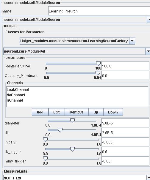
Figure 29 : Parameters defining a Learning_Neuron.
Close the window. Create two populations of Learning_Neuron (Learning_Neuron0 and Learning_Neuron1). The structure of each population must be a neuroml.model.network.Grid3DStructure, and each slider must be set at 1,1,1 . In the "ExternalIntensity subpanel", dt must be set to 0.1 . "step" must be ticked. The following array must be 10 columns wide and on line large. This means that each neuron will sustain an external current, which is supposed to last for 10 times (columns) * 0.1 s = 1s . Each line corresponds to the current input for each neuron. The input current to be typed is 1e-9 A . As for Learning_Neuron0 , this input must be typed for the cells under the following columns (Time 1, Time 3, Time 5, Time 8).
As for Learning_Neuron0 , this input must be typed for the cells under the following columns (Time 1, Time 3, Time 5, Time 8) (Figure 32). As for Learning_Neuron1 , this input must be typed for the cells under the following columns (Time 1, Time 3, Time 5, Time 7 and Time 9). Close.
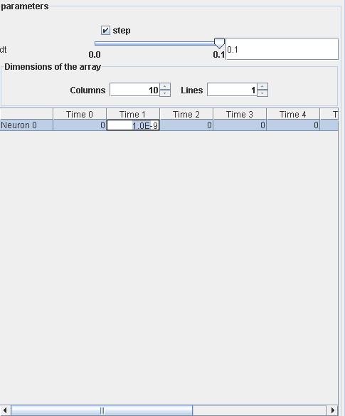
Figure 30 : Defining the intensity curremt.
Create one probe. Name it _Probe_ . It must be a neuroml.model.Network.ModuleProbe. The class must be set to Holger_modules.module.multiProbe.ProbCtrlFactory. NumProbes must be set a 2 : it will receive the input from both Learning_Neuron0 and Learning_Neuron1.
Let's add a Projection now. The source must be Learning_Neuron0 and the destination Learning_Neuron1. Make it a general projection and rename it GenProj. The source method must be a Holger_modules.module.sourcemethod.MatrixConnection (allows specifying which neurons in the source population connects to which neuron in the destination population). The source port must be 1 (which is the port for spikes). The matrix must have 1 column and 1 line. The cell must be ticked to indicate that neuron 0 of the source population connects to neuron 0 of the destination population. The "DestMethod" must be a Holger_modules.module.shmemNeuron.LearningDestMethod . Dynamic synapses are added through this method. The synaptic weight of the synapse varies according to the input and reaction of the receiving neuron [1]. The values are to be set as following : "delay", 0.025 ; "Excitation_factor", 0.5 ; "Synaptic_Weight", 0.3 ; "tau_rec", 3.0 ; "tau_in", 0.003 ; "tau_facil", 0.3 ; "Learning_step", 0.02 ; "recovered_prop", 1.0 ; "active_prop", 0.0 ; "inactive_prop", 0.0 (Figure 31).
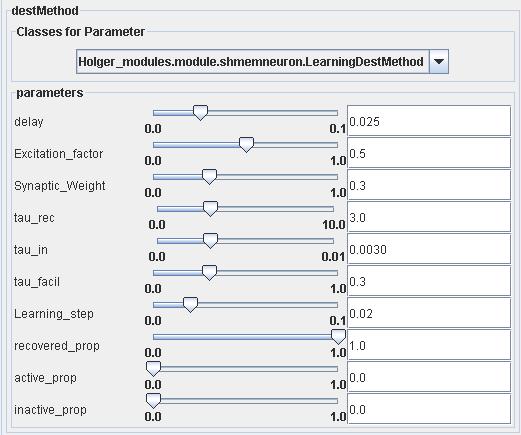
Figure 31 : Synaptic parameters.
You should now add two attachments on the network design panel. Both should have _Probe_ as a destination. Both attachments should be neuroml.model.network.ModuleAttachment. The source population of the first one (which should be named ModuleAttachmentSource) should be Learning_Neuron0 and the source population of the second one (which should be named ModuleAttachmentDestination) should be Learning_Neuron1. For both the source method should be Holger_modules.module.Source_FirstOnly.Source_FirstOnly with a "CellID" set to 0 (the index of the first neuron in each population) and a source port set at 2 (source port for measurements).
The destination method for both attachments should be a Holger_modules.module.multimeter.Multimeter. The display parameters defer slightly. We want ModuleAttachmentSource to display its result first ("panelNdx" set to 0) on half the screen (height set in % to 50). The results should be processed after 0.025 s (delay set to 0.025) . The destination port should be set to 2 (2 is the port for measurements), and the title should be source neuron.
We want ModuleAttachmentSource to display its result afterwards ("panelNdx" set to 1) on half the screen ("height" set in % to 50). The results should be processed after 0.025 s (delay set to 0.025) . The destination port should be set to 2 (2 is the port for measurements), and the title should be destination neuron.
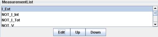
Figure 32 : The measurements list
Now it is time to select the measurements list of ModuleAttachmentSource to be sent, select the item called "Not_I_Ext", click on the "Edit" button below (Figure 34). A small window appears. Be sure to select neuroml.model.MeasurementTool.CellInternalIntensity, and tick to_be_sent (Figure 33). Close the window. You can notice that "Not_I_Ext" has been renamed "I_Ext". This measurements allows to check the external current going in the source neuron. Select the item called "Not_V", click on the "Edit" button below. A small window appears. Be sure to select neuroml.model.MeasurementTool.CellInternalIntensity, and tick "to_be_sent". Close the window. You can notice that "Not_V" has been renamed "V". This measurements allows to check the membrane voltage in the source neuron.
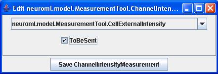
Figure 33 : Selecting the measurement to be sent
Proceed similarly with ModuleAttachmentDestination. Select the Not_LearningFactor_0 (which corresponds the synaptic weight[1]) and proceed as explained previously to ensure its value will be sent. Select the X_Concentration_0 (which to the concentration of active resources[1]) and proceed as explained above in order to ensure its value will be sent. The index of 0 corresponds to the index of the synapse to be monitored on the neuron.
Now your network should be displayed as below (Figure 34).
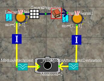
Figure 34 : Learning Network
The simulation parameters need to be defined as displayed in Figure 35.
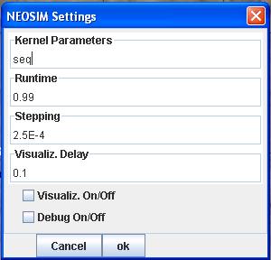
Figure 35 : Simulation parameters
Now you don't want to lose your hard work, save the file under the name "LearningNeuron.xml". Run the simulation as explained in Tutorial 3.
If you double click on the probe at the end of the simulation, you will get the following results (Figure 36).
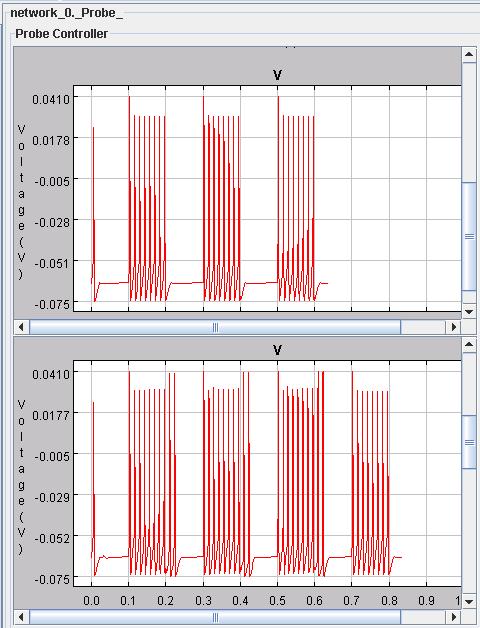
Figure 36 : Membrane voltages of the source and destination neurons
[1]Serge Thill. One Shot Sequence Learning in a Reccurent Neural Network with Dynamic Synapses. Msc Thesis. 2002. University of Edinburgh.