V.4 Tutorial 4: Capturing a network and reusing it
Complicated networks can be designed by different users and they might decide to merge their networks into a bigger one. It is also possible that some small networks can be reused. Therefore a network design tool should include a facility in order to capture and reuse the small networks. This tutorial explains how to define a network and to reuse it in another network.
Run the GuiKit as explained in section II of this user guide. Load FirstModel.xml that has been defined in Tutorial 2. Edit the population node NewPop0. Reduce the number of neurons in NewPop0 to 20. Close the population node editing window. In the networks window click on the button "Add". A new network design window appears. Change the name of your new network from Network_1 to MediumNetwork. Add two population nodes "ImplementationNeuron", now add four projection links which allow you to interconnect all population nodes alltogether. The number of neurons both "ImplementationNeuron" should be 15. The parameters of each projection link should correspond to Figure 10, except of course the source and destination population nodes. MediumNetwork should look like Figure 18.
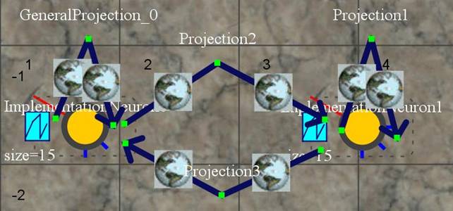
Figure 18: MediumNetwork
Now close the network design window. Open network_0 (select it and click
on "edit"). Add a "MediumNetwork" to the editing panel. Please note that
MediumNetwork_index is not MediumNetwork. It is a copy of
MediumNetwork with the same properties as MediumNetwork. Add four
projection links to the network design panel . Two links should have NewPop0 as a
source and MediumNetwork_index as a target. Two links should have as a
source MediumNetwork_index and NewPop0 as a target. Edit the new
projection links, and give them the same parameters as explained in
Figure 10,
except for the sources and destination populations.
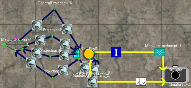
Figure 19: The main network of network_0
You might have noticed that things became a bit complicated in the tree panels allowing to choose the source and destination population nodes (Figure 20).
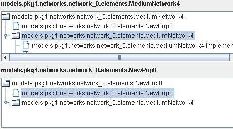
Figure 20: Tree panel for the choice of the source and the target of the projection
As you can see, you can select a population node belonging to MediumNetwork5.
Please ensure that the four projections are distributed as described below:
1st projection: from models.pkg1.networks.network_0.elements.NewPop0 to models.pkg1.networks.network_0.elements.MediumNetwork4.Implementation0.
2nd projection: from models.pkg1.networks.network_0.elements.NewPop0 to models.pkg1.networks.network1.elements.MediumNetwork5.Implementation1.
3rd projection: from models.pkg1.networks.network_0.elements.MediumNetwork5.Implementation0 to models.pkg1.networks.network_0.elements.NewPop0.
4th projection: from models.pkg1.networks.network_0.elements.MediumNetwork5.Implementation1 to models.pkg1.networks.network_0.elements.NewPop0.
Please note that you need to specify a root network on the top right panel entitled "Select the Main Network". The current one is models.pkg1.networks.network_0, and normally it is already selected by default. Save the NeuroML model under the name NetworkCaptured.xml.
Now run NMLPlay as explained in section II of this user guide. Load the model NetworkCaptured.xml and run the simulation.
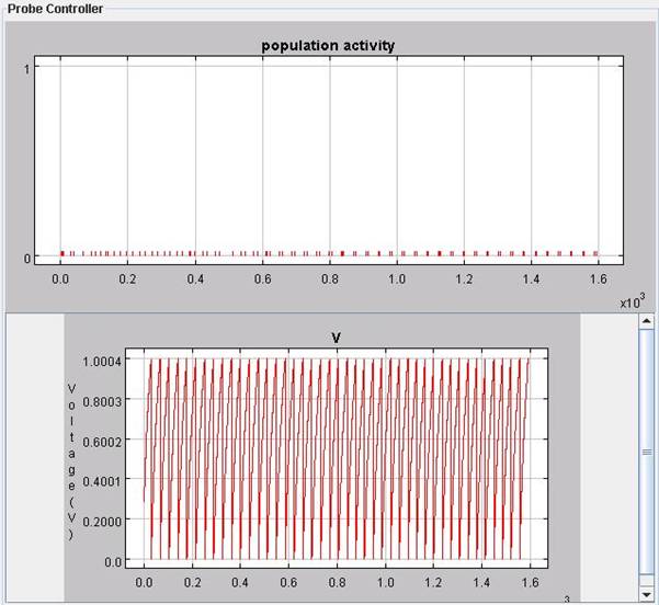
Figure 21: results from the simulation of the model defined in NetworkCaptured.xml
If you compare Figure 22 with Figure 18, you will notice that the spiking pattern measured on the neuron 7 of ImplementationNeuron0 from network1 is very similar (the initial voltage is random, hence it will differ slightly). However, the spiking activity is much sparser in Figure 22. Indeed, the spiking activity is only measured on the 20 neurons of ImplementationNeuron0 from network1.
In this tutorial, a new network equivalent to the network from Tutorial 2 has been defined. It is a very theoretical tutorial, but the possibility to capture real subnetworks can allow dealing with very complicated network in a very user-friendly and clear manner.